Removal:
Overview:
The removal of the console made it easier to do the work on the computer, but it is also possible to leave the console in place and simply open and remove the circuit boards. The main issue in doing it this way is that you will have to remove the glue holding the circuit board to the retaining posts before being able to get to the screws holding the circuit board to the case. This is trivial if you have a hair dryer handy, otherwise it might be wise to remove the whole unit so that you can work on it better.
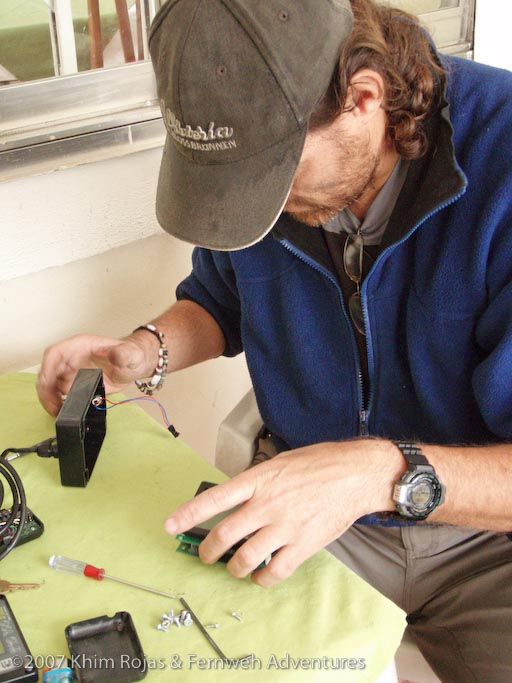
Before starting make sure you have access to someone who can solder, or are able to solder circuit boards and have the right equipment. The work is trivial but requires some precision soldering. In my case I got the work done at a tv repair shop and it took all of 5 minutes and cost me 5$
Additionally, a hair dryer is very handy, or alternatively, an exacto knife.
To finish the work I used some high temp gasket material I had to replace the glue I removed. Neoprene glue would also work. Whatever you use it should not be too fluid as it would then just run all over the place. Not only that it should also be something which you can fairly easily remove next time...
Procedure:
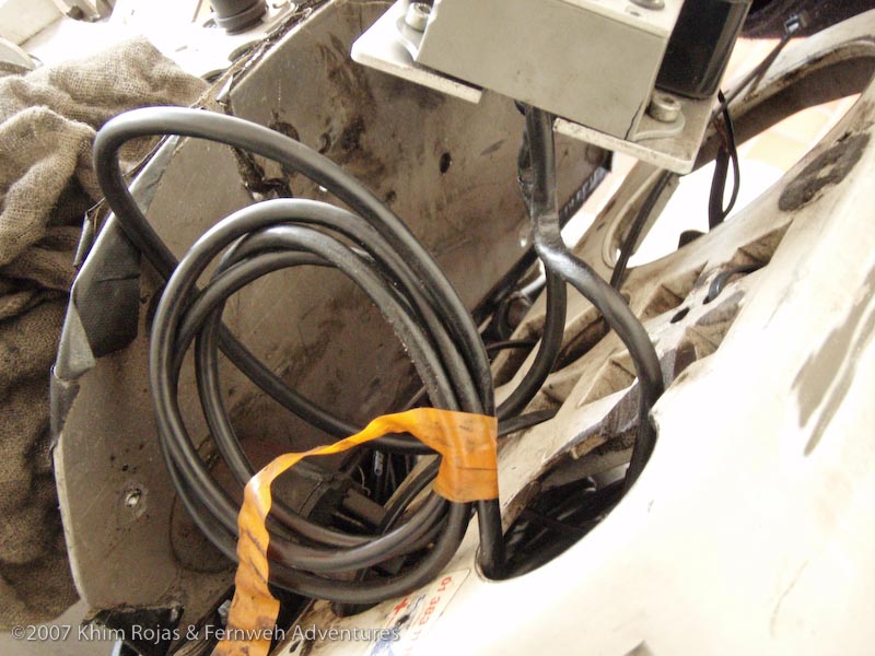
Before starting, remove the negative connection from the battery so that there is no power in the system. Underneath the fairing/console there a are a number of "live" wires so in case they come loose there could be a short (e.g. the accessory power plug).
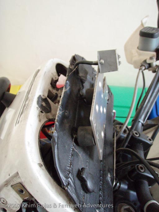
I removed the fairing, turn signals and the side covers, so that I could get to the aluminum base plate holding the computer console plate in place. The aluminum base which holds the computer console plate, is held to the old plastic console by a number of small phillips head screws with 8mm nuts. So this procedure takes a while. (Your bike will have a different setup, as this is something I manufactured myself to hold the Touratech computer).
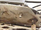
Once the aluminum base plate is free, there are two bolts holding the computer console plate to the aluminum base. Removing these leaves you holding the computer console plate holding the computer and the idiot lights.

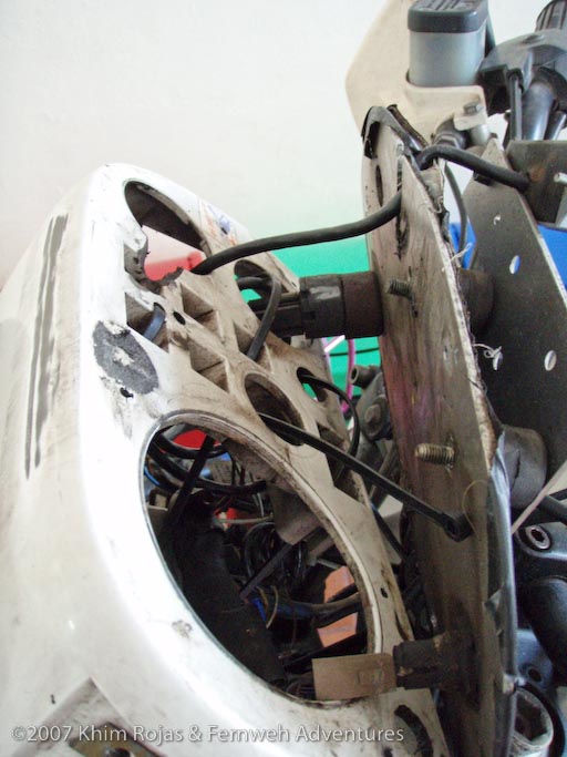
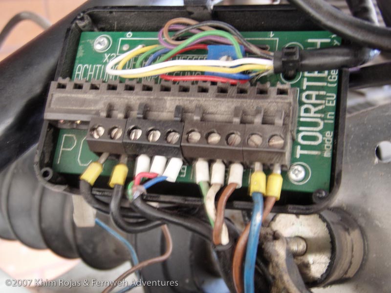
In order to remove the whole console I also had to take the computer cables off the connector box inside the fairing. Simply pop the cover, and unscrew all the pins holding the various cables. (If you choose to leave the console in place this step is not necessary, skip to the part about removing the glue below.)
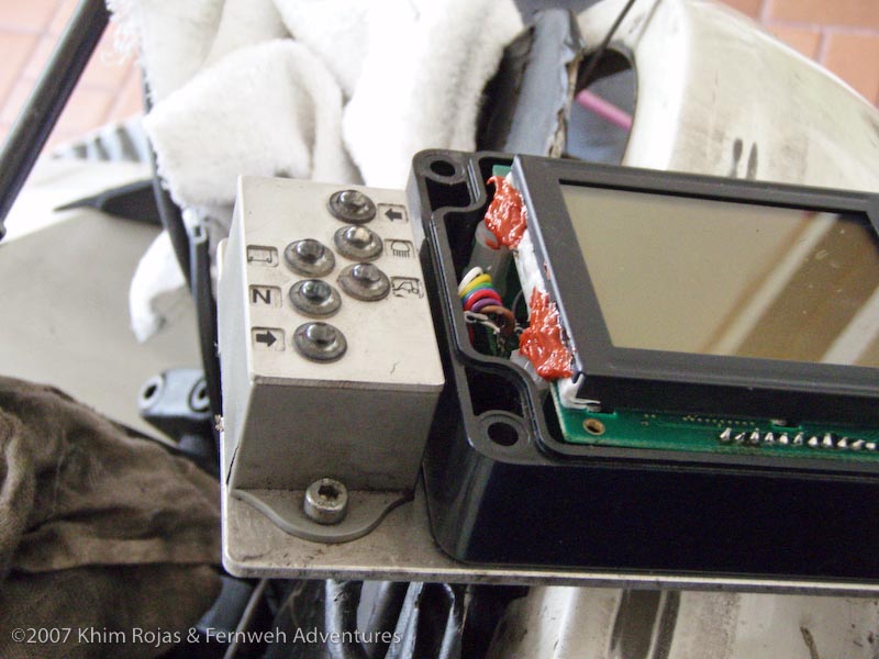
The next step is to remove the idiot lights from the console followed by the computer itself.
To remove the computer from the console plate, you need to remove the cover of the computer, and unscrew the 4 screws holding the computer console to the plate.
Once these are all removed the computer console is free and you can continue to work somewhere away from the bike.
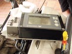
The Computer:
Overview:
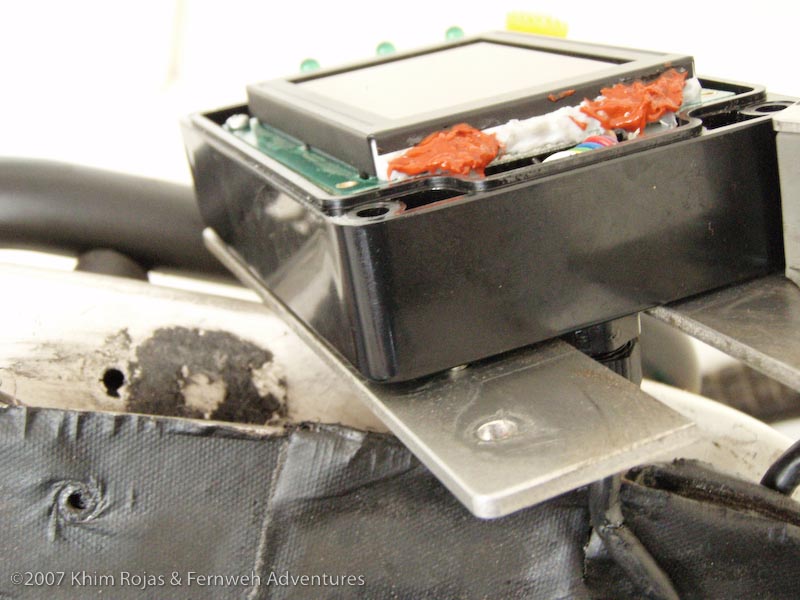
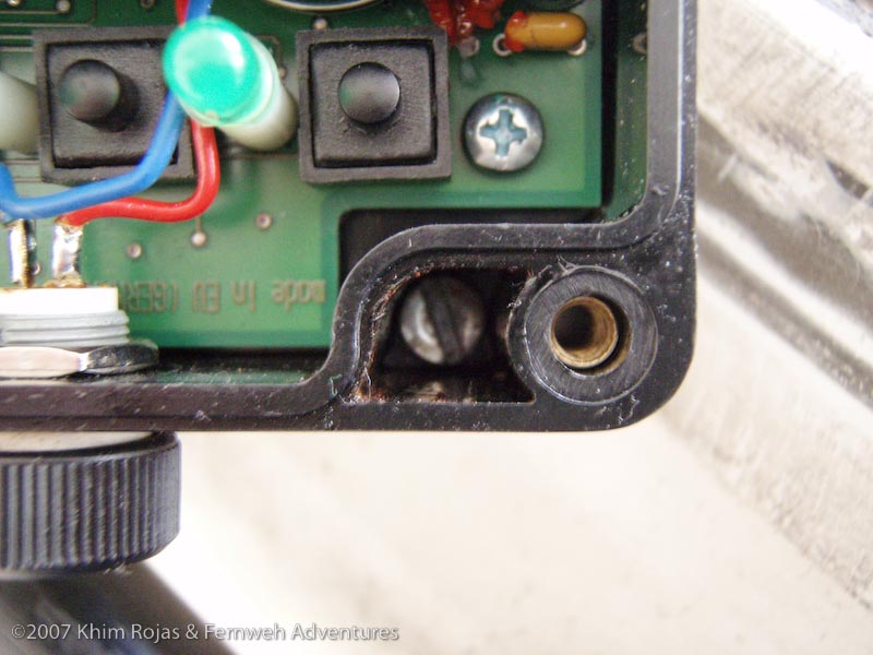
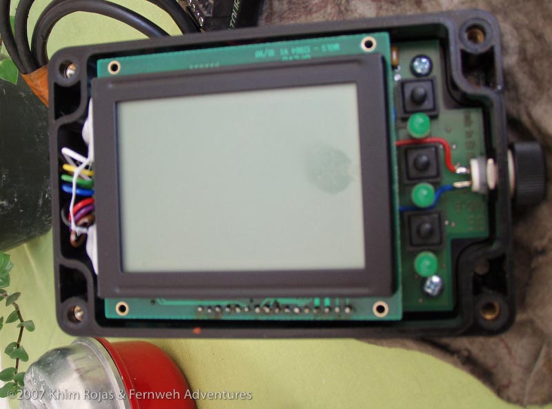
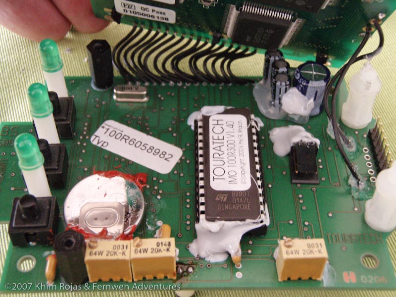
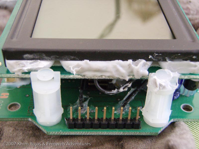
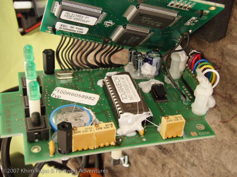
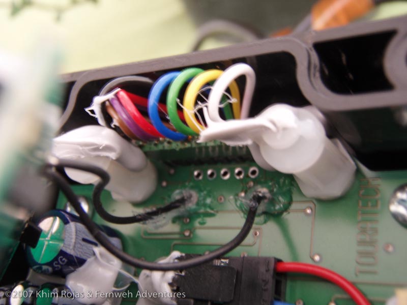
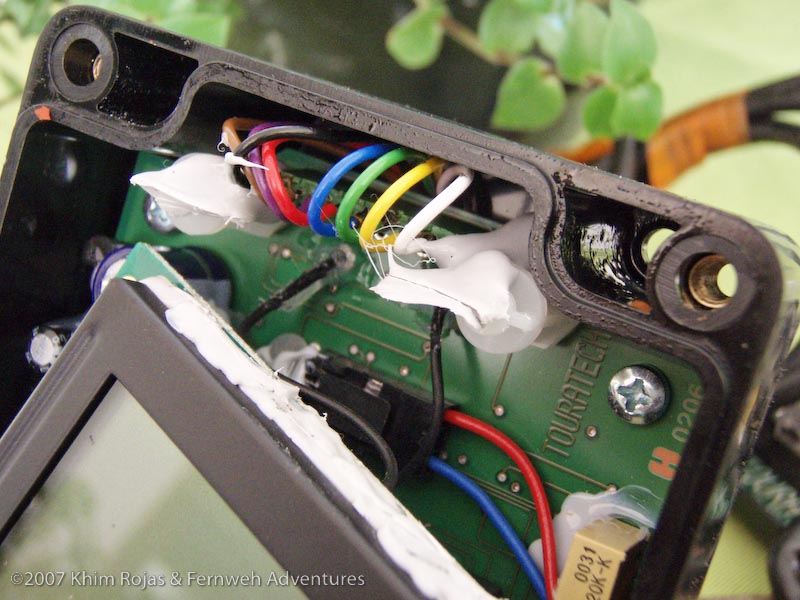
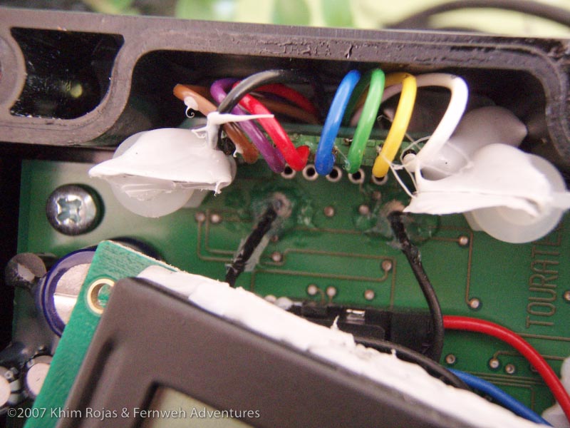
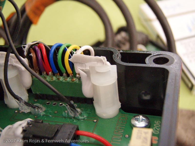
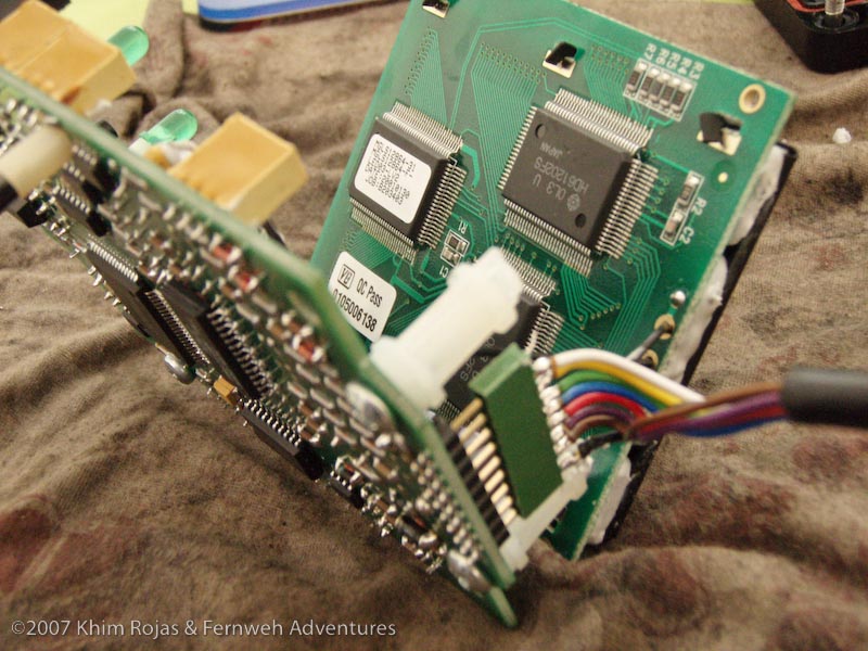
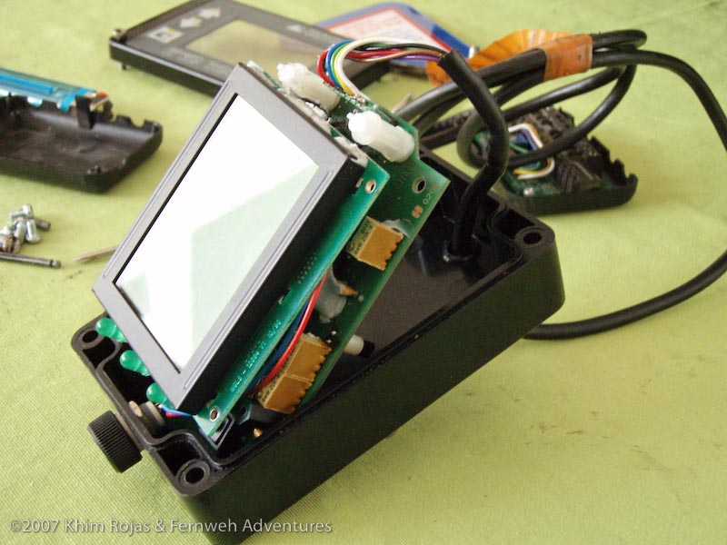
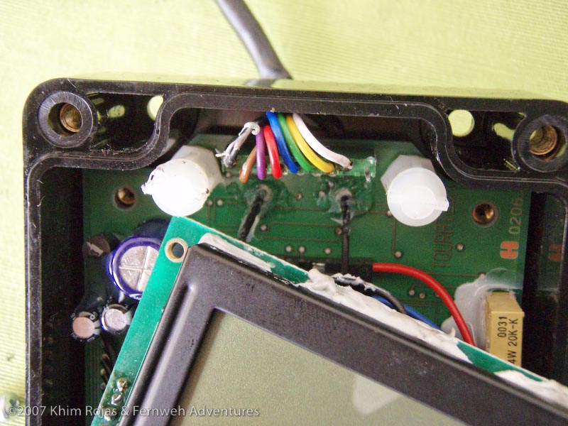
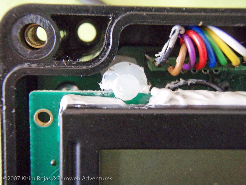
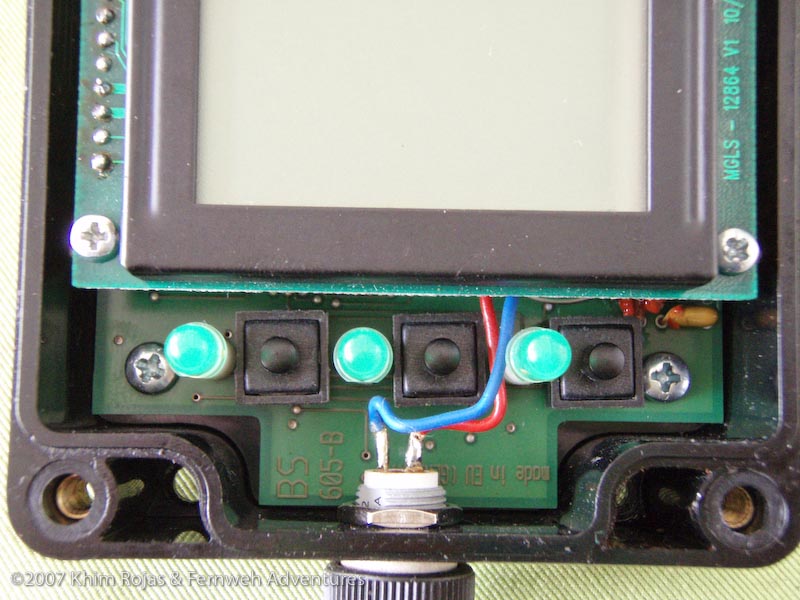
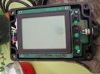
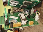
The computer consists of two circuit boards on top of each other, held together by two screws in the front (by the contrast adjustment knob), and in the back by being inserted into two posts and glued in place.
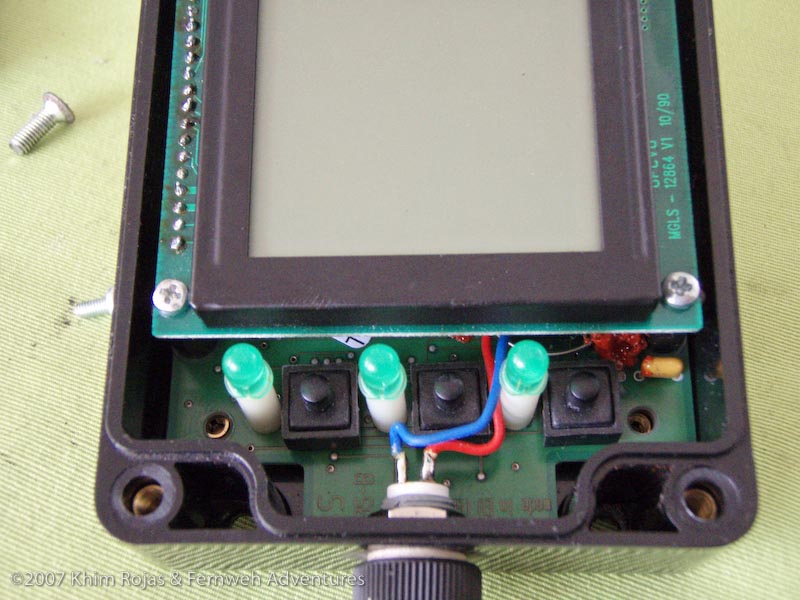
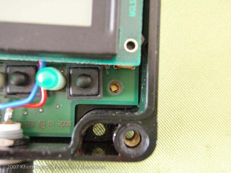
Four screws hold the bottom circuit board to the casing.
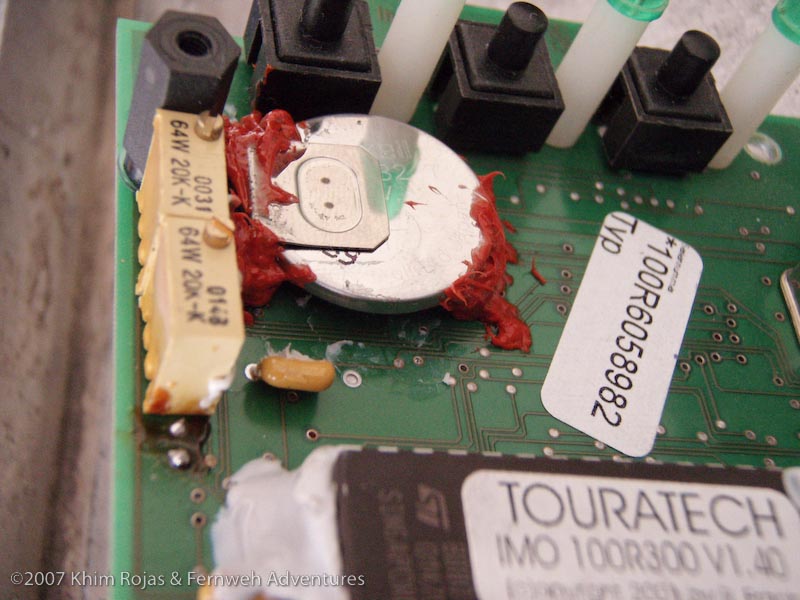
In order to remove the glue holding the top board to the posts as well as the glue holding the battery, the best way is to use a hair dryer. By heating the glue you can easily remove it. Alternatively it is possible to cut the glue away (very, very carefully), and thereby freeing the various components.
Procedure:
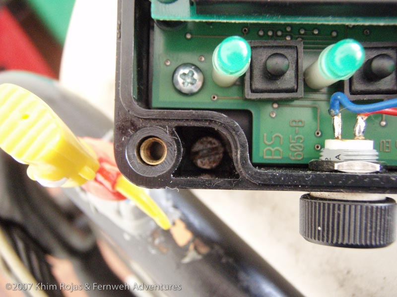
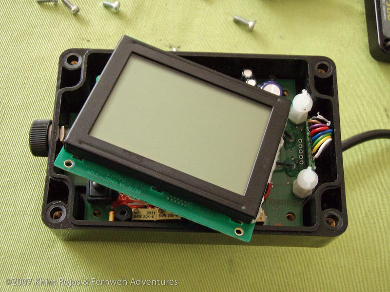
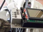
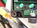
First, remove the two screws at the back of the top circuit board. Then, using a small exacto knife I carefully cut the glue around the posts in the front of the top circuit board. Once I cut enough of the glue away the top board was free, and folded away from the bottom board.
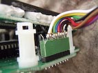 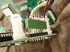
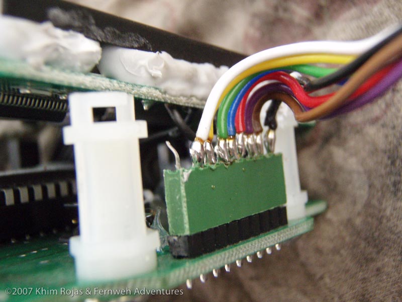
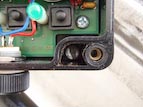
Once the top board is free, I removed the cable connector (this, in my case was also held together by glue to the posts). (in the photo above they circuit boards had already been removed from the casing)
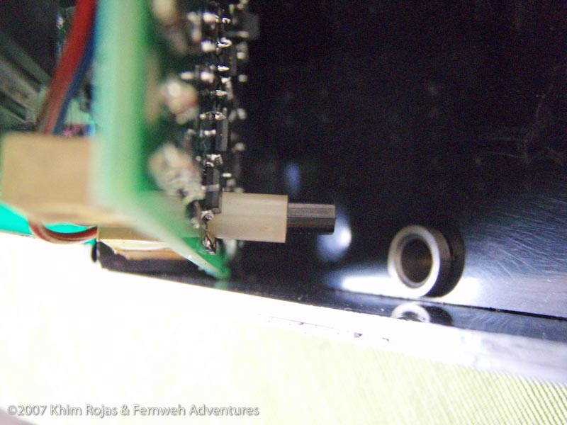
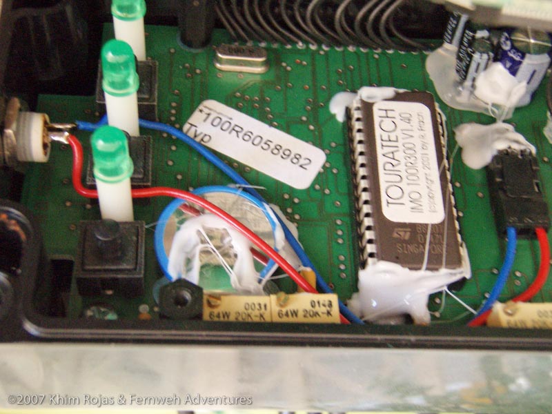
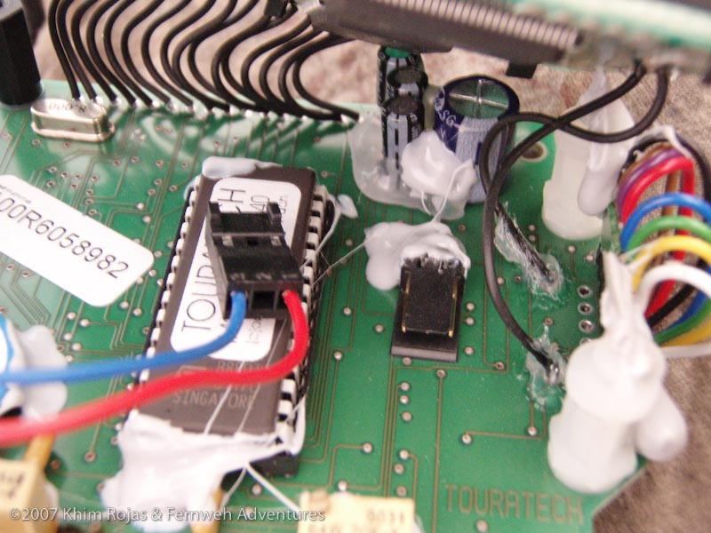
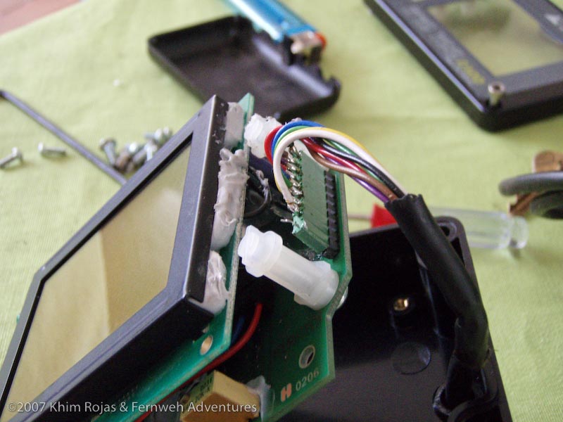
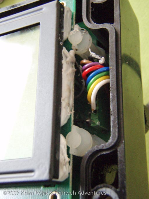
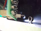
Next remove the cable connecting the contrast adjustment knob to the circuit board. It simply pulls straight out. (see the a picture in the right column)
Once the cables are free, you can remove the 4 screws holding the circuit board to the case.
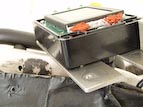
With everything free the two circuit boards will come out, be careful with the temperature sensor which fits into the case, and the contrast adjustment knob on the front of the board.
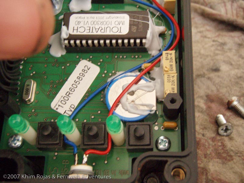
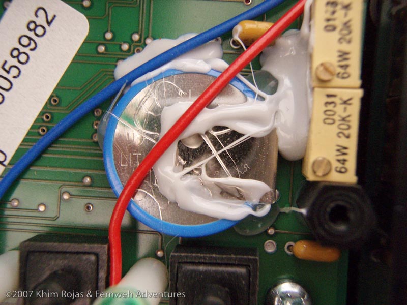
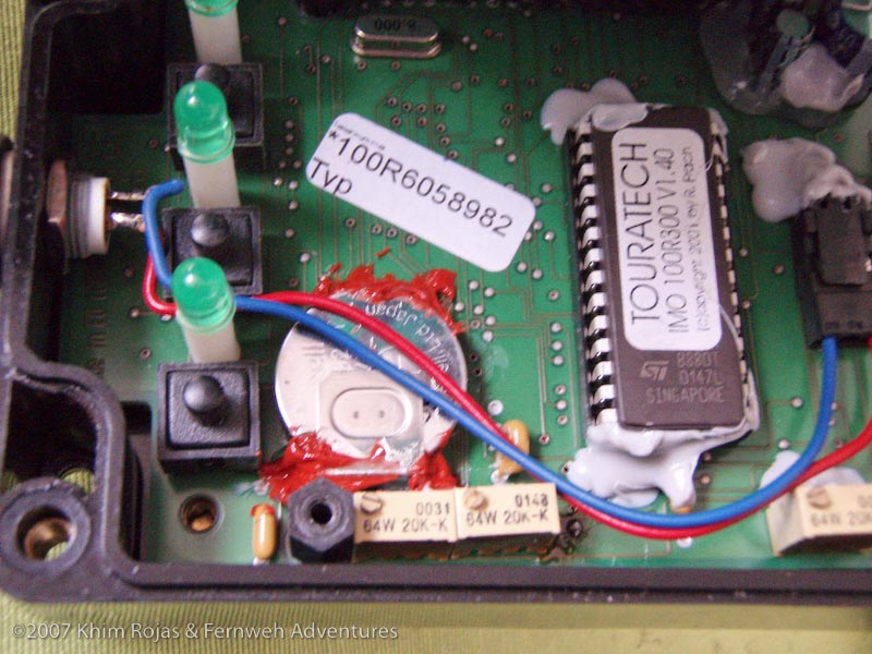
Battery:
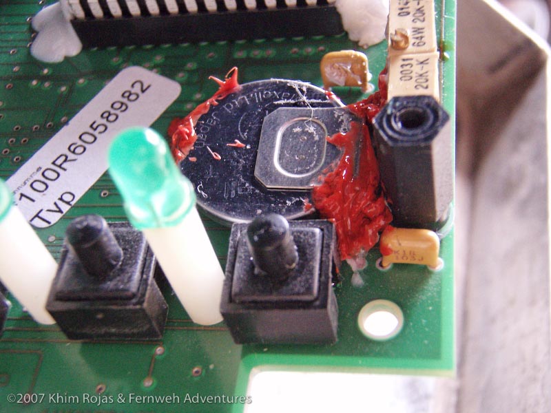
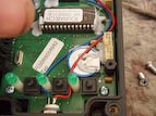
With the unit in your hand you can now swing the top back carefully and access the battery. There is glue holding the battery in place and as vibration insulation. Remove all the glue so that when you heat the pins on the reverse side the battery just comes straight out. (or the technician does it.)
Take the unit and the spare battery (you have a spare right?) to the technician and have him remove the old one and solder the new on in place. Keep in mind that the battery does not sit flush with the bottom circuit board. Rather it sits up, the pins on the base holding the battery will not allow it to go through the circuit board, so don't try and force it. (or allow the technician to try).
Once the new battery is in place (and soldered). Put some silicone sealer, gasket material, neoprene glue or some other insulation/glue material in the same places as it was before. Make sure to give it time to dry before continuing on with the remaining steps.
Re-assembly:
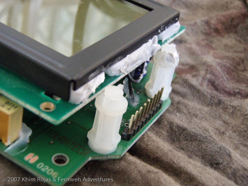
There is not anything particularly spectacular about re-assembly. Just reverse your previous steps. Don't forget to put glue on the posts holding the top circuit board to the bottom one.
Additionally, don't forget to connect the contrast adjustment screw.
Be careful when fitting the circuit boards into the plastic casing, do it by getting the circuit board underneath the contrast adjustment and then dropping the rest in, taking care with the temperature sensor.
Make sure to let all the glue dry before closing everything.
Before mounting everything, I tested that the computer worked by connecting the cabling and powering the system up (including connecting the battery). Once I was sure that he unit functioned at least as well as previously, I went ahead and closed everything up, and mounted everything.
Conclusion:
The work is do able, but would have been a lot easier to do if I had a hair dryer. Nevertheless, by cutting, and carefully prying the glue (using a small screwdriver, or my leatherman), it was possible to remove it all and free all the components.
|